

IoT module · LAN Ethernet · DIN rail
BIOS-IO-02 – LAN Ethernet I/O module with relay outputs: 4 isolated digital inputs + 4 relay outputs
Read digital signals and control signalling or simple actuators/output/control devices over the LAN – in one module, with no programming, configured in a web browser and with data in JSON format.
- 4 isolated digital inputs: 0–24 V voltage or dry contact with 24 VDC biasing, selected with a DIP switch, pulses up to 3 kHz
- 4 NO relay outputs: isolated, max. 2 A, static ON/OFF or pulse operation
- Ethernet 10/100 Mbit, HTTP JSON: configured in a web browser, no programming
- 35 mm DIN rail, 12–36 VDC supply from terminals or Passive PoE via RJ45
What is the BIOS-IO-02 LAN Ethernet I/O module with relay outputs?
BIOS-IO-02 is a universal IoT module for reading digital signals and controlling simple actuators/output/control devices in machines, equipment, robots and controllers. It combines 4 isolated digital inputs with galvanic isolation and 4 independent NO relay outputs. It communicates over Ethernet using HTTP with data in JSON format and mounts on a 35 mm DIN rail. If you only need to read signals, choose the BIOS-IO-01 module with 8 digital inputs.
The type of each input is set with a DIP switch: a 0–24 V voltage input or a dry-contact input with built-in 24 VDC biasing, e.g. for volt-free contacts and contactors. The inputs can also work as pulse counters at frequencies up to 3 kHz. The inputs are optically isolated (input current typ. 2.0 mA, isolation withstand 2000 VDC) and share a common COM.A bank, and each channel has a pair of COM.A and IN+ terminals.
The relay outputs are isolated, with NO contacts rated up to 2 A and a life of 5×10⁶ cycles. Each output can work statically (on/off) or in periodic (cyclic) mode, in which the relay switches itself on and off at set intervals. LED indicators show the status of the inputs, outputs and the device.
The module connects to the LAN via 10/100 Mbit Ethernet (RJ45) and is configured in a web browser. Other systems, such as MES, SCADA or your own application, can read the status of the inputs and outputs through the module’s HTTP JSON API. The module is powered from the POWER INPUT terminals (12–36 VDC, SELV) or via Passive PoE through the RJ45 socket; power consumption is max. 1.5 W at 24 VDC. It has built-in reverse-polarity, thermal and overload protection. An auxiliary 24 V / 40 mA output is available on the AUX OUT terminals.
The manufacturer provides a two-year warranty on the device and post-warranty service for 10 years from the date the device is placed on the market.
BIOS-IO-02 technical specifications
| Parameter | Value |
|---|---|
| Digital inputs | 4, isolated (galvanic isolation, optical isolation) |
| Input type | 0–24 V voltage (active at 12–24 V) or dry contact with 24 VDC biasing |
| Input type selection | DIP switches |
| Input current | typ. 2.0 mA |
| Isolation withstand | 2000 VDC |
| Pulse input | yes, max. 3 kHz |
| Relay outputs | 4 (OUT.5–OUT.8), isolated, NO, max. 2 A, life 5×10⁶ cycles |
| Auxiliary output | AUX OUT terminals (+, −): 24 V / 40 mA |
| Output operating mode | static ON/OFF, pulse operation (periodic mode) |
| Indication | LED indicators: input and output status, device status |
| Communication | Ethernet 10/100 Mbit, RJ45 socket |
| Supported protocols | DHCP, TCP/IP, UDP, HTTP, JSON |
| Configuration | web browser |
| Power supply | POWER INPUT terminals: SELV 12–36 VDC; RJ45 socket: Passive PoE |
| Power consumption | max. 1.5 W at 24 VDC |
| Built-in protection | reverse polarity, thermal, overload |
| Terminals | screw terminals 0.35–2.5 mm² (AWG 24–14), max. 0.8 Nm |
| Mounting | 35 mm DIN rail, any orientation |
| Enclosure | ABS UL94V-0, light grey, 6×DIN |
| Dimensions | 107 × 90 × 65 mm |
| IP rating | IP20 |
| Protection class | III / SELV |
| Operating temperature | −40…+60 °C |
| Storage temperature | −40…+85 °C |
| Humidity | RH < 90 %, non-condensing |
| Weight | 170 g |
| Compliance | EC Declaration of Conformity No. 01/2024 (BIOS-IO-01…08 modules): EMC 2014/30/EU, RoHS II 2011/65/EU |
| Warranty | 2 years; post-warranty service for 10 years from the date the device is placed on the market |
BIOS-IO-02 photos
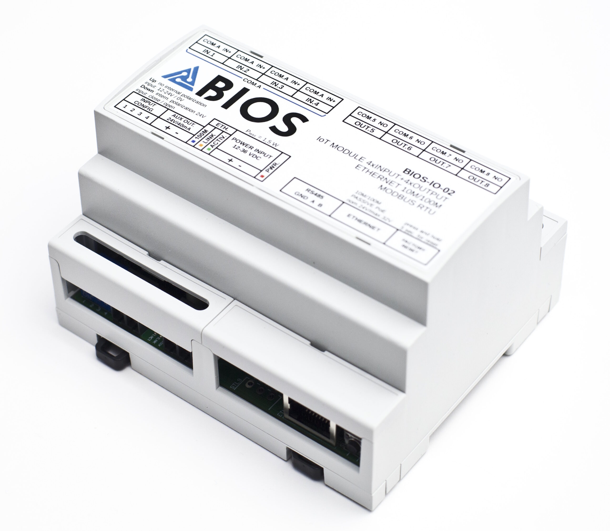
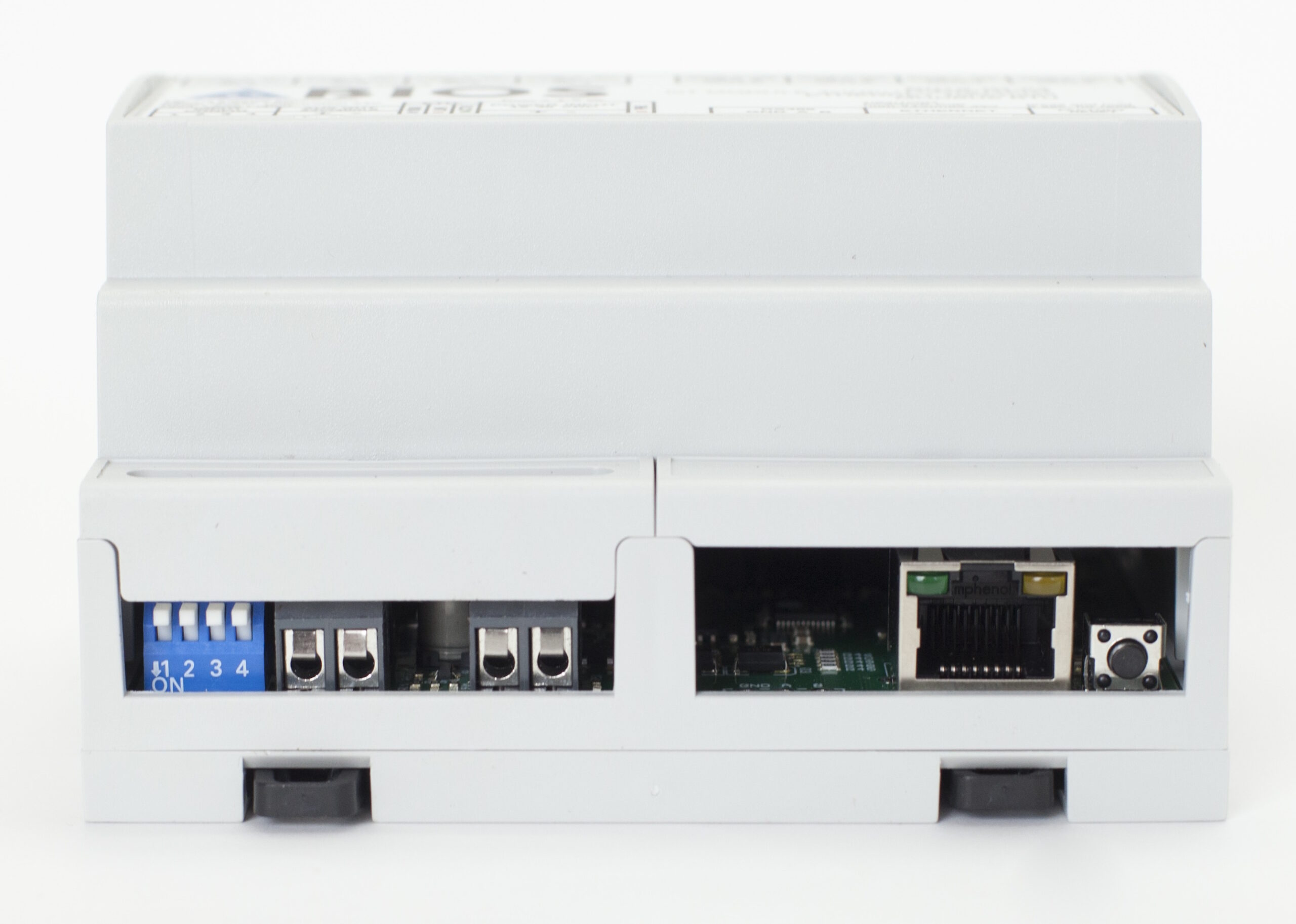
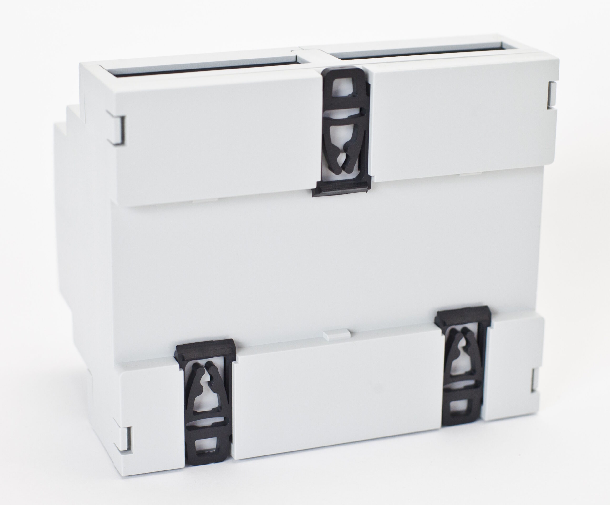
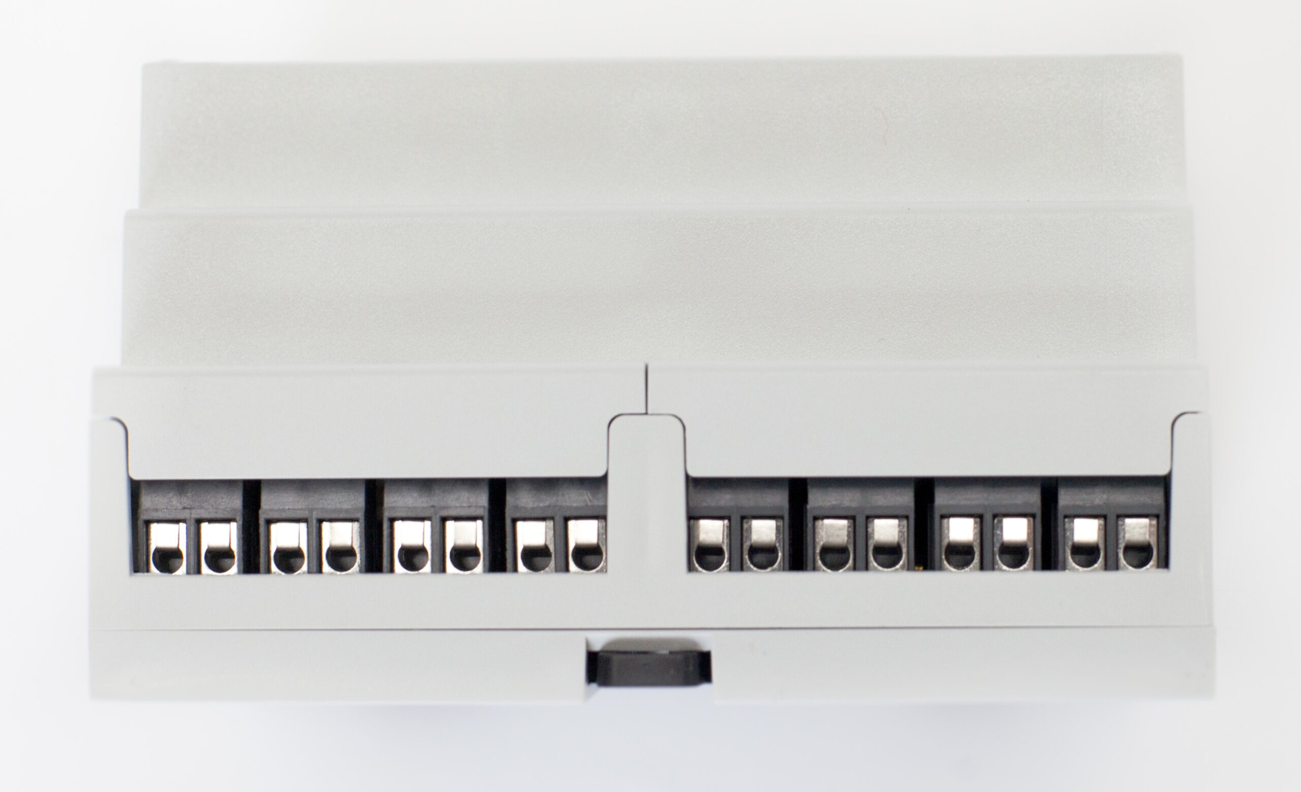
Applications
- Status signalling: controlling lamps, beacons and signal towers through the relay outputs, including in flashing (periodic) mode.
- Remote switching of devices: simple actuators/output/control devices controlled from a server or system over the LAN.
- Reading machine status with simultaneous control: the inputs read run, alarm or stop signals, while the outputs control signalling or devices at the same location.
- Contacts, contactors and voltage signals: dry-contact inputs for volt-free contacts and 0–24 V voltage inputs.
- Integration with IT systems: reading input and output status over HTTP JSON from an MES, SCADA or your own software.
- Machine monitoring in Scout MES: BIOS-IO-02 lets you connect conventional machines, which cannot provide data directly over the LAN, to Scout MES.
- Welder monitoring with BIOS-CT-01: the BIOS-CT-01 current-draw detection sensor works with the inputs of the BIOS-IO-02 module.
- More inputs, no outputs: if you only need to read 8 signals, see BIOS-IO-01.
Example wiring
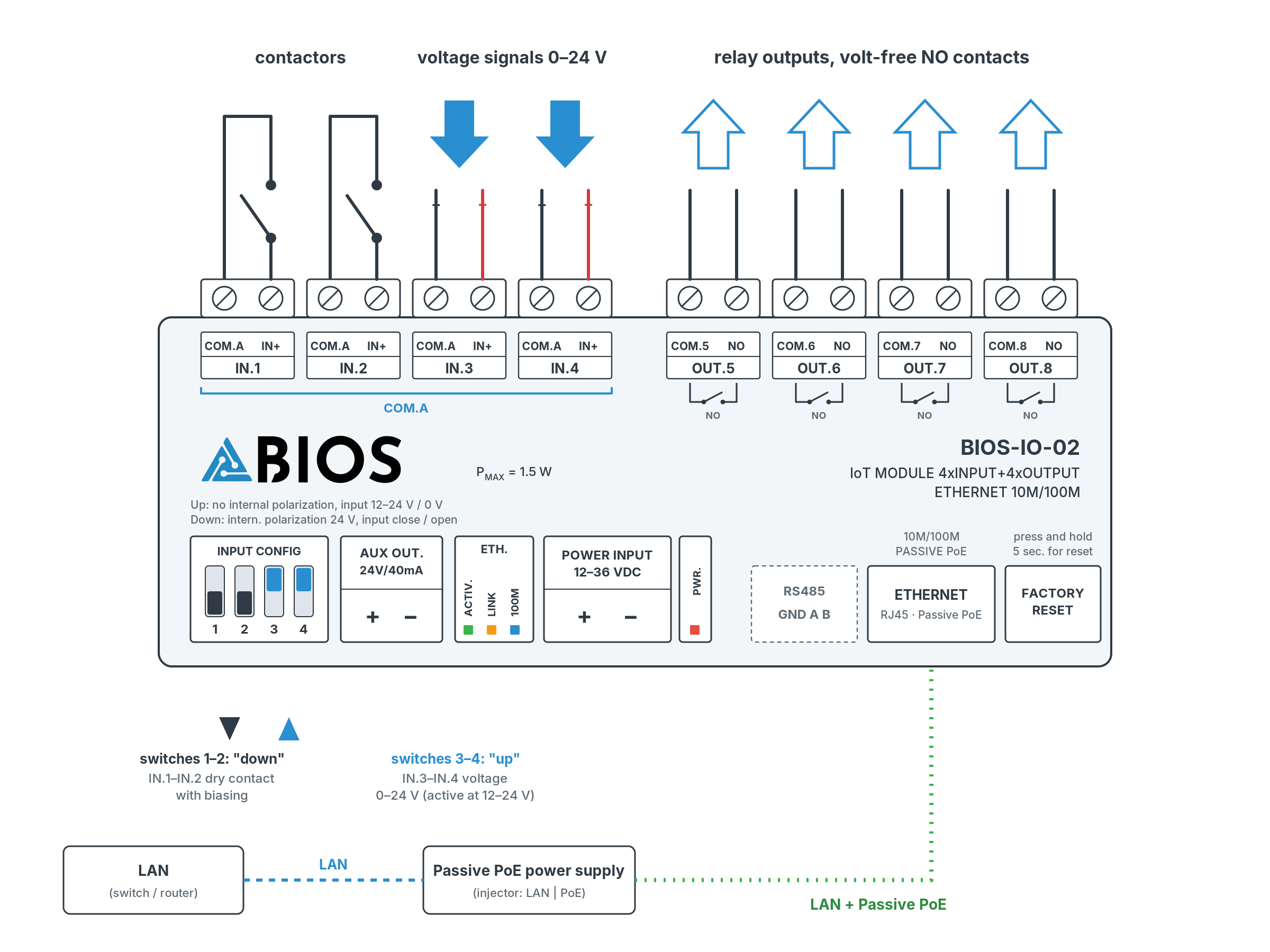
JSON data example
The current status of the inputs and outputs is returned by the GET /state/get request (no login required). The response is an array of 8 objects: positions 1–4 are the inputs, positions 5–8 are relay outputs OUT.5–OUT.8.
- Inputs:
isActive– whether the input is currently active;counter– input activation counter. - Outputs:
isOn– the output is switched on;isActive– momentary relay state;isPeriodMode– periodic (cyclic) mode;counter– output switch-on counter. - Rules for outputs: when
isOn=true, in periodic modeisActivecan betrueorfalse(the relay switches on and off cyclically), and without periodic modeisActiveis alwaystrue. WhenisOn=false,isActiveis alwaysfalse.
[
  { "isActive": true,  "counter": 13 },
  { "isActive": false, "counter": 12 },
  { "isActive": false, "counter": 8 },
  { "isActive": true,  "counter": 7 },
  { "isActive": true,  "isPeriodMode": true,  "isOn": true,  "counter": 13 },
  { "isActive": false, "isPeriodMode": true,  "isOn": true,  "counter": 12 },
  { "isActive": false, "isPeriodMode": false, "isOn": false, "counter": 8 },
  { "isActive": true,  "isPeriodMode": false, "isOn": true,  "counter": 7 }
]
Controlling the outputs and configuring periodic mode require login; we do not publish the details.
Frequently asked questions about BIOS-IO-02
BIOS-IO-02 is a DIN-rail IoT module with 4 isolated digital inputs and 4 relay outputs that communicates over Ethernet in HTTP JSON format. It is used to read signals and control simple actuators/output/control devices in machines and equipment.
No. The module is configured in a web browser, and data is read over HTTP in JSON format.
Each input can work as a 0–24 V voltage input (active at 12–24 V) or as a dry-contact input with built-in 24 VDC biasing, e.g. for volt-free contacts and contactors. The mode is set with a DIP switch.
The outputs have isolated NO contacts rated up to 2 A, e.g. for signalling or simple actuators/output/control devices. The outputs are labelled OUT.5–OUT.8, and each has its own pair of COM and NO terminals.
In periodic mode, a switched-on output cycles on and off by itself at set intervals, e.g. for flashing signals. In the status readout this is shown by the pair of fields isOn (output switched on) and isActive (momentary relay state).
Through the module’s HTTP JSON API. The GET /state/get request returns the status of the 4 inputs (isActive, counter) and the 4 outputs (isOn, isActive, isPeriodMode, counter).
From the POWER INPUT terminals with 12–36 VDC (SELV) or via Passive PoE through the RJ45 socket, using the same cable that carries the data. Power consumption is max. 1.5 W at 24 VDC.
On a 35 mm DIN rail, in any orientation. The enclosure measures 107 × 90 × 65 mm and takes up 6 DIN modules; wires are connected to screw terminals.
At temperatures from −40 to +60 °C and humidity below 90 % RH, non-condensing. The enclosure is rated IP20, so the module is installed in a control cabinet.
Yes. The module is covered by EC Declaration of Conformity No. 01/2024 (EMC Directive 2014/30/EU and RoHS II Directive 2011/65/EU).
BIOS-IO-01 has 8 isolated digital inputs and is used only for reading signals. BIOS-IO-02 has 4 isolated digital inputs and 4 NO relay outputs, so in addition to reading it can also control, e.g. signalling. Both modules have the same input type, Ethernet communication with HTTP JSON and a 6×DIN enclosure.
Yes, the outputs can be switched on and off via the module’s API, and periodic mode can be set on them. Controlling the outputs requires logging in to the module, while the status readout (GET /state/get) is available without login.
By default the module has the static IP address 192.168.31.4 (subnet mask 255.255.255.0, DHCP disabled). To restore the factory settings, press and hold the “Factory reset” button next to the Ethernet connector for 5 seconds, then release it.
The manufacturer provides a two-year warranty on the device and post-warranty service for 10 years from the date the device is placed on the market. The warranty covers all material and manufacturing defects.
Yes. Scout MES uses BIOS-IO modules to monitor conventional machines that cannot provide data directly over the LAN.
Request a quote
Need BIOS-IO-02 for your installation, not sure whether to choose BIOS-IO-01 or BIOS-IO-02, or want to check whether the module suits your machines? Write or call us and we will select the right solution and prepare a quote.
Phone: +48 880 366 728 · E-mail: info@bios-iot.com
Manufacturer: INTSOL sp. z o.o., ul. Radarowa 60, 02-137 Warszawa