
IoT System · Modbus RTU · GSM/LTE · Microsoft Azure · web visualisation
BIOS IoT system – IoT remote monitoring and remote telemetry, from PLC to web visualisation
We supply the whole stack: a GSM/LTE gateway and modules for Modbus RTU devices, the secure Microsoft Azure cloud and a web visualisation with alarms, tailored to your sites. We deploy quickly and provide full support.
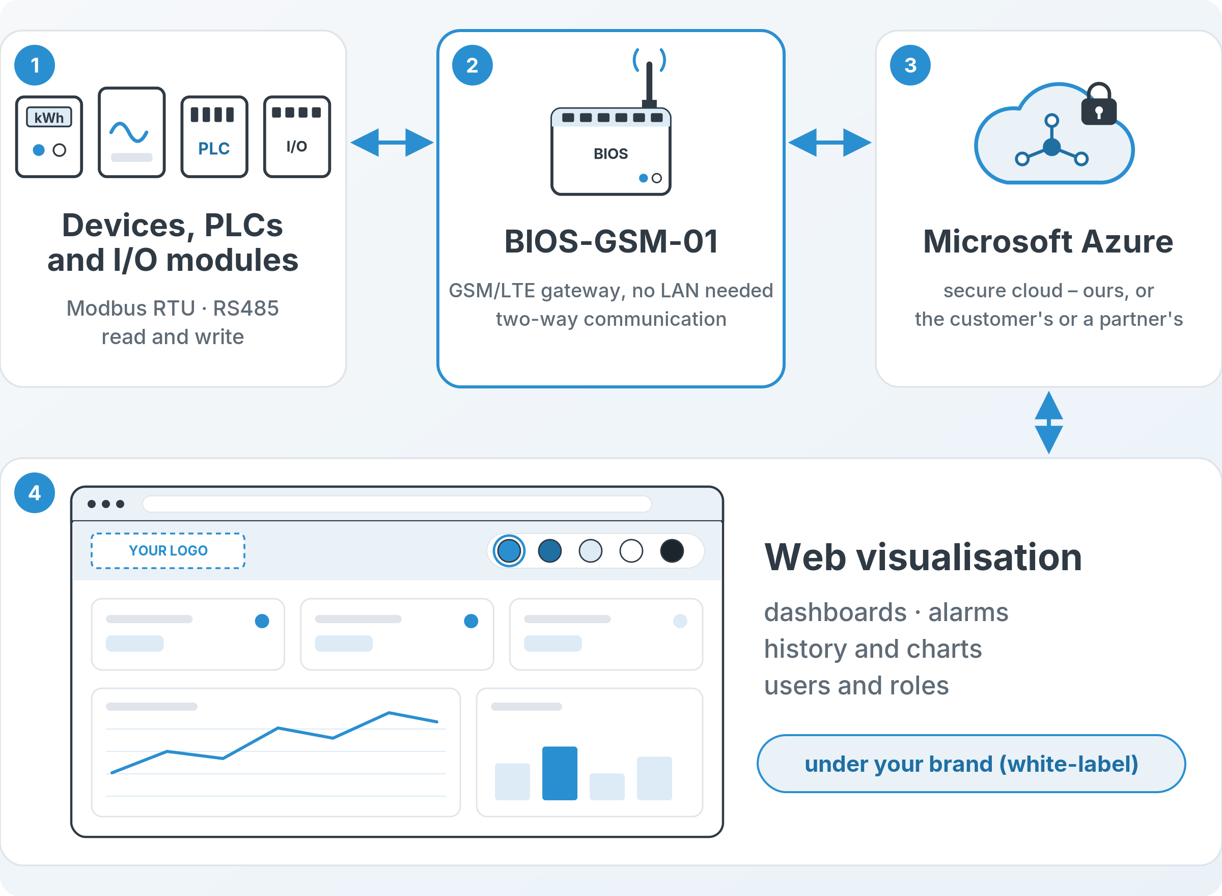
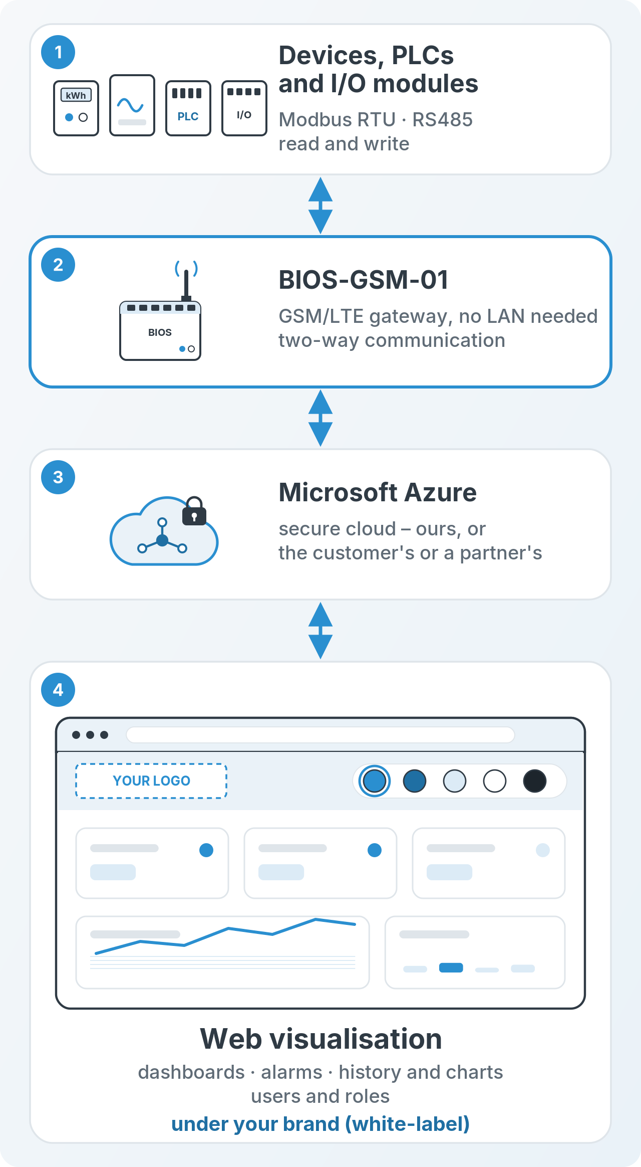
- Devices, PLCs and I/O modules (Modbus RTU): read and write over RS485
- BIOS-GSM-01 GSM/LTE gateway: no LAN needed on site, two-way communication
- Secure Microsoft Azure cloud: ours, or the customer’s or a partner’s
- Web visualisation: dashboards, alarms, history and charts, users and roles
- White-label: the system under your brand – see Partners
What is the BIOS IoT System?
The BIOS IoT System is a complete solution for remote telemetry and remote control: it connects devices, sites, PLCs and I/O modules with Modbus RTU to the secure Microsoft Azure cloud and to a browser-based visualisation. Data from the devices is collected by the BIOS-GSM-01 GSM/LTE gateway and sent over the mobile network via MQTT with SSL encryption to Microsoft Azure IoT Hub. Communication works both ways: write commands can also be sent to the devices from the visualisation.
The visualisation and the whole system run in the secure Azure cloud. The Azure IoT Hub service can be provided by us, or it can be the customer’s or a partner’s cloud – we agree this during deployment. We build the web visualisation for each specific customer: real-time dashboards, site status visualisation, alarms, history and charts, and users and roles. This is the IoT SCADA approach: instead of a local operator station you get web SCADA in a browser, and the site does not need a LAN.
We supply the whole stack – hardware, connectivity, cloud and visualisation – so you have one supplier from commissioning to day-to-day operation. You will find our other modules and products on the BIOS IoT website. For device manufacturers and partners we also offer the system as a white-label solution, under their own brand – see Partners.
How the IoT remote monitoring system works – components and diagram
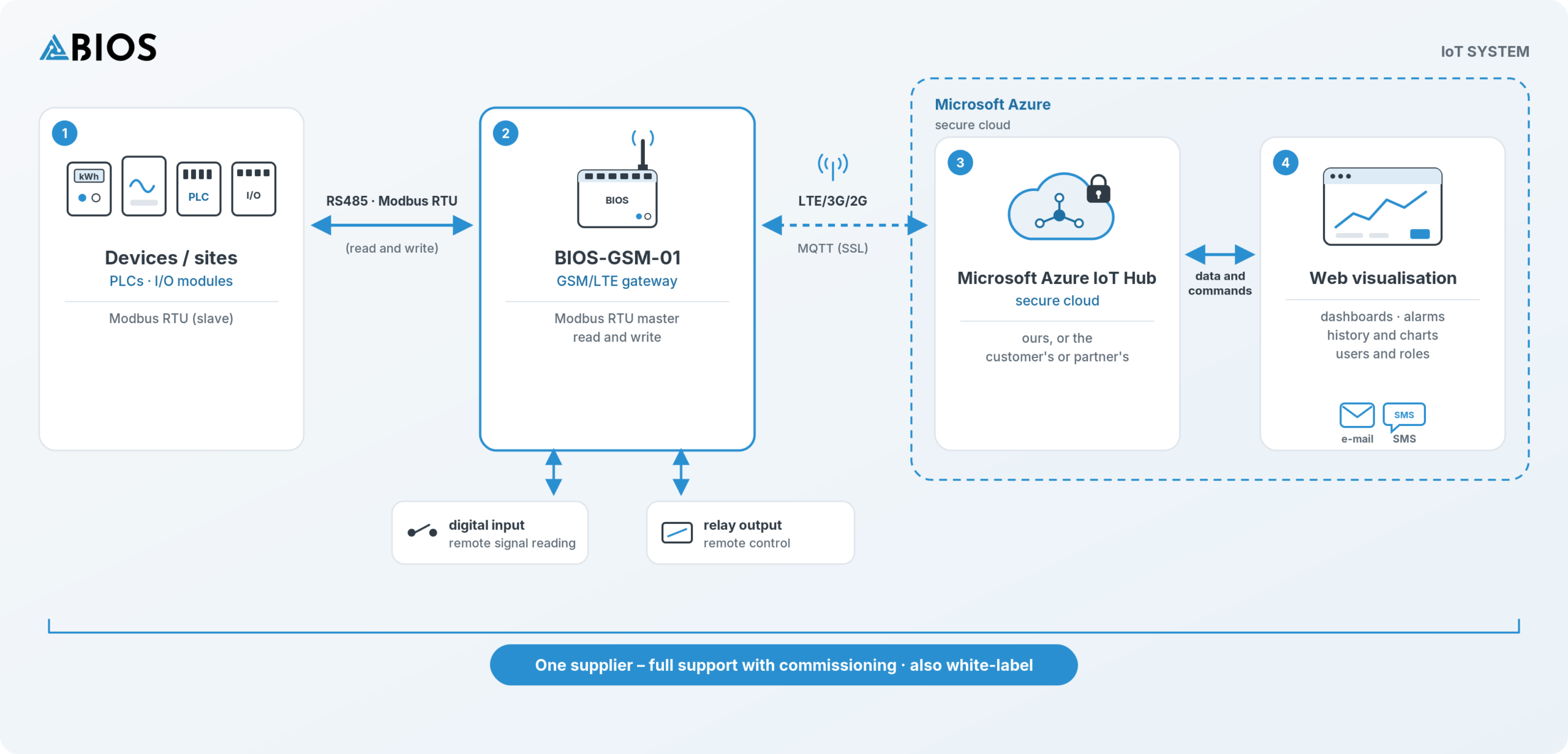
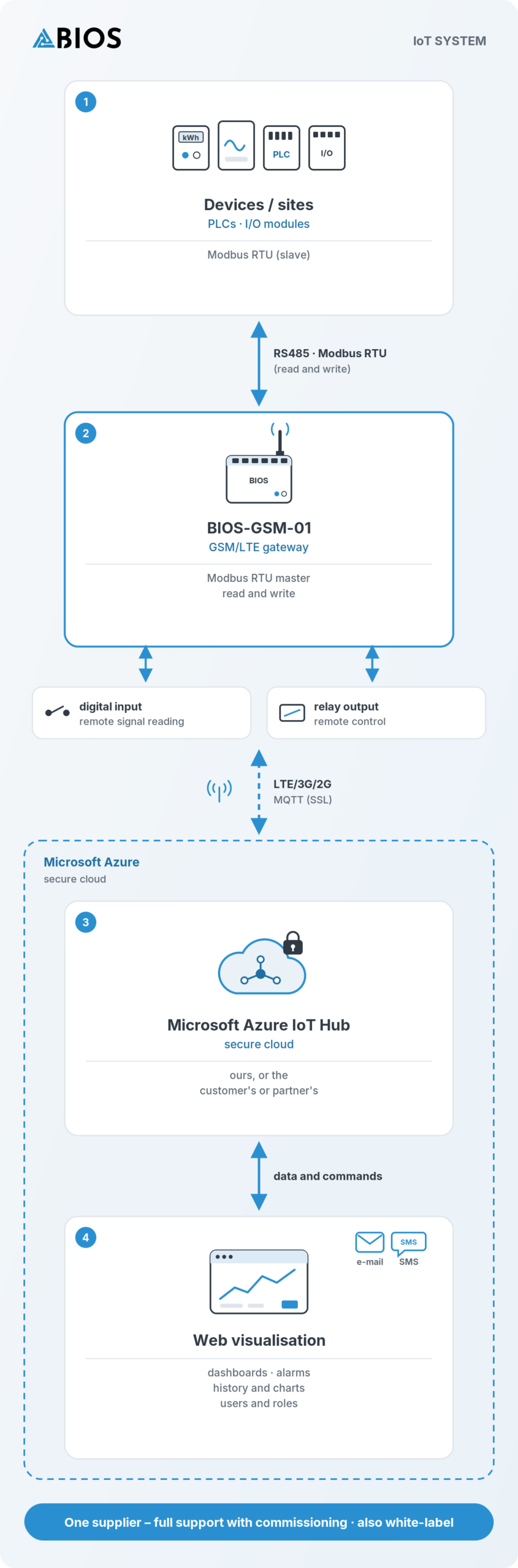
The system consists of four layers, and data and commands flow both ways:
- Devices, sites, PLCs and I/O modules: meters, inverters, controllers and other devices work as Modbus RTU slaves on an RS485 bus.
- BIOS-GSM-01 gateway: a module for 35 mm DIN rail. As Modbus RTU master it reads data and writes device registers, and it exchanges data with the cloud over the LTE/3G/2G mobile network (microSIM, private APN) via MQTT (SSL). It also has its own isolated digital input and 2 A NO relay output – for remote signal reading and remote control.
- Microsoft Azure IoT Hub: the secure cloud in which the system runs – ours, or the customer’s or a partner’s, to be agreed during deployment.
- Web visualisation: real-time dashboards, site status visualisation, alarms, history and charts, users and roles. Commands can be sent to the devices from the visualisation.
Alarms: e-mail notifications as standard, SMS via an SMS gateway. A dedicated app with push notifications is in preparation.
IoT remote telemetry: applications
Each application assumes that the site has a device with Modbus RTU (controller, meter, inverter, regulator, I/O module) or a simple signal connected to the gateway input. The measured parameters come from these devices – the gateway does not measure them itself.
Tanks and containerised fuel / AdBlue stations
We monitor data from the tank’s controller or measuring devices with Modbus RTU, e.g. level and alarms, dispenser deliveries counted from pulses on the gateway input, and the state of an alarm contact. You know how much fuel is left and how much has been dispensed without visiting the site. You get an e-mail or SMS alarm when the level is low or there is a fault, and you have a history of deliveries.
LPG and LNG stations at customer sites
We monitor parameters from the station’s controllers and transmitters with Modbus RTU, e.g. tank level, pressure and alarm states. You plan deliveries according to the actual stock, not a schedule – fewer empty tanker runs and a faster response to alarms.
Generators and backup power
We monitor data from the generator controller via Modbus RTU (if the controller provides it), e.g. running and ready status, alarms, operating hours and fuel level. The gateway input can take an additional signal, e.g. fault or running from the ATS automation. You see the whole fleet in one place: which generators are ready, which are in fault, and when a service is due. Especially useful for rental and service companies.
Containerised boiler houses (biomass, gas, oil, steam)
We monitor data from the boiler or boiler-house controller and heat meters with Modbus RTU, e.g. temperatures, operating status, alarms and consumption. The gateway’s relay output lets you switch a simple actuator/output/control device on or off remotely. An unmanned boiler house is under constant supervision, and you learn about a fault quickly.
Energy storage, charging stations and energy meters
We read energy meters, inverters, controllers and BMS that provide Modbus RTU, e.g. energy, power, states and alarms. You get a remote view as well as history and charts of energy consumption or production across distributed sites, and servicing is simpler.
Grain storage and drying
We monitor data from dryer controllers and grain temperature measurement systems with Modbus RTU, as well as the operating status of the fan or dryer from the gateway input. The farmer and the service team see the site status in a browser on a phone or computer and get an alarm before the grain overheats. No LAN is needed on site.
Commercial refrigeration: cold rooms, monoblocks, refrigerated cabinets and lockers
We monitor data from the controllers of refrigeration units and equipment with Modbus RTU, e.g. temperatures, operating states and alarms. A temperature alarm goes straight to the owner and the service team, and the temperature history helps with HACCP documentation. The service team knows the fault before the technician sets off.
Gas infrastructure and cathodic protection of pipelines
We monitor parameters of cathodic protection stations and gas station equipment with RS485 Modbus RTU, e.g. voltages, currents, states and alarms. Remote supervision of equipment spread along the network means fewer inspection rounds and parameter history at hand.
Who the BIOS IoT System is for
- Equipment manufacturers (OEM): add remote monitoring and control to your product, also under your own brand (white-label) – without building your own IoT team. See Partners.
- Rental companies (generators, boiler houses, containers): you see the operation and status of every unit at the hirer’s site, operating hours and alarms.
- Service and maintenance companies: you learn about faults quickly, diagnose remotely and plan visits.
- Operators of distributed infrastructure (gas stations, tanks, energy storage): all sites in one visualisation, with history and charts.
- Utility and fuel suppliers (LPG, LNG, diesel): you plan deliveries according to the actual stock at the customer’s site.
- Integrators and automation companies: you connect your customers’ Modbus RTU sites to the cloud without building your own platform.
Benefits of the BIOS IoT System
- Fast deployment: the gateway connects to the cloud over the mobile network, so there is no need to build a LAN on site.
- The whole stack from one supplier: we supply hardware designed and manufactured by us, configure the Azure cloud and build the visualisation – no need to combine solutions from several companies.
- 100% control over the hardware: the hardware is designed and manufactured by us, so we have full control over it.
- White-label: the system under your brand – for equipment manufacturers and partners. See Partners.
- Full support: from selecting the hardware and the Modbus register map, through commissioning and configuring the gateway, to the cloud and visualisation.
- Two-way communication: reading data and sending write commands to devices, as well as remote control of the gateway’s relay output.
- Alarms wherever you are: e-mail as standard, SMS via an SMS gateway, and soon a dedicated app with push notifications.
- Visualisation tailored to the customer: real-time dashboards, site status, history and charts, users and roles – your device’s parameters, not a generic panel.
- Secure cloud: the system runs in Microsoft Azure, and the gateway sends data via MQTT with SSL encryption, also via a private APN.
Frequently asked questions about the IoT system
The BIOS IoT System is a complete solution for remote telemetry and control: devices, PLCs and I/O modules with Modbus RTU, the BIOS-GSM-01 GSM/LTE gateway, the secure Microsoft Azure cloud and a web visualisation tailored to the customer. We supply the whole stack.
No. The BIOS-GSM-01 gateway connects to the cloud over the LTE/3G/2G mobile network with a microSIM card, also via a private APN.
Devices that communicate via Modbus RTU over RS485, such as PLCs, meters, inverters and I/O modules. The gateway works as a master and supports read and write.
Yes. Communication is two-way: write commands can be sent from the visualisation to Modbus RTU devices, and the gateway’s relay output can be controlled remotely.
It is the system’s web visualisation: real-time dashboards, site status visualisation, alarms, history and charts, and users and roles. It runs in a browser and is built for each specific customer.
E-mail notifications are standard, and we send SMS messages via an SMS gateway. We are also preparing a dedicated app with push notifications.
The visualisation and the whole system run in the secure Microsoft Azure cloud. You do not need your own cloud: the Azure IoT Hub service can be provided by us, but it can also be the customer’s or a partner’s cloud – we agree this during deployment.
Yes. The system is available as a white-label solution for equipment manufacturers and partners. Details on the Partners page.
Yes. The gateway sends data via MQTT with SSL encryption to Microsoft Azure IoT Hub.
We agree the billing model and SIM cards individually with each customer when quoting the deployment.
We do. We deploy quickly and provide full support with commissioning and configuring the gateway, cloud and visualisation – you have one supplier for the whole system.
Request a quote
Want to remotely monitor and control Modbus RTU devices where there is no LAN, or offer such a system under your own brand? Tell us about your device – we will prepare a deployment proposal and a quote for the whole system.
Phone: +48 880 366 728 · E-mail: info@bios-iot.com
Questions about deployment and support: Contact and support